| Home | Store | Blog | Forums | FAQs | Lesson Plans | Pictures |
|
#1
 10-09-2009, 02:54 AM
|
|||
|
|||
|
I am familiar with the nutrient temp needing to be around 68-72 degrees to mimic what's in the ground. I was wondering if anyone has any information on what problems might arise if the nutrient temp goes much lower than say 50 degrees?

|
|
#2
10-10-2009, 04:37 AM
|
|||
|
|||
|
Quote:
") In case outside temperatures are getting low and the nutrient temperature drops to (let's say) 15C/59F or below, one may consider heating the nutes up to 20-22° C with a 10 bucks aquarium heater. What will happen actually when nute temps (and/or outside/room temps) will drop under 50 degrees? Nothing fancy, the available oxygen in the nutrients will increase somewhat but the general metabolism and uptake of plants will be much lower, - until stagnation. PS: with low temperature of nutrients the EC should be higher to encourage osmosis.
|
|
#3
10-10-2009, 05:35 AM
|
|||
|
|||
|
Quote:
Quote:
I don"t have a EC meter and wont any time soon, But because that is a way of telling how strong the nutrient mix is I am assuming that in general that in cold areas (temps) a stronger nutrient mix is best because of osmosis. So because of the general temps the nutrients should be stronger? Last edited by GpsFrontier; 10-10-2009 at 06:03 AM.
|
|
#4
10-10-2009, 07:48 AM
|
|||
|
|||
|
Quote:
 . It is important in the context of the solution I may have. . It is important in the context of the solution I may have.I perhaps need to do a drawing or 3D simulation, and look up a few technical terms, (non-native writers run out of vocabulary sometimes) so hang on there! 
|
|
#5
10-10-2009, 09:15 AM
|
|||
|
|||
|
Quote:
Sorry, I cant get the scanner to work right now and it is around 5:30 am here but I do have a to scale drawing of the back yard. Hopefully I can get the scanner to work tomorrow.
|
|
#6
10-10-2009, 10:57 AM
|
|||
|
|||
|
Hi again!
Ok, let me just briefly explain what it is about before getting involved (both of us) in something that is out of question. I am not sure if it is a appropriate system for several reservoirs with that much space in between. I've once build (long time ago) a floatation tank that held nearly 1000 Liter (some 250 gallons) of water that needed to be heated and kept constantly at 34.5°C in a rather cool environement (indoors though). I did so with a small 2Kw water heater (we call that "under sink water boiler") and a few meters of garden hose, a small water pump, plus some plumbing fittings and simple house hold stuff. If it happened that you already have a used 2-3 Kw electric water heater (because these aren't exactly cheap), it's done in a day. Closed hot water circuit but not under pressure. No supplementary electronics needed, if the heater has a simple but "continuously variable" temp regulation. I am not sure about the terminology here but I bet you know what I am talking about. So please, tell me if such a solution is of interest for you and if you got the stuff or are willing to get it in case... Cheers, Luches
|
|
#7
10-11-2009, 02:55 AM
|
|||
|
|||
|
Quote:
|
|
#8
10-11-2009, 03:12 AM
|
|||
|
|||
|
Mine was actually not tank less, it had a 5 liter tank. Those were cheaper at the time, as the tankless model had to be more powerful (3-4Kw at least) Think it over and tell me if you need a complete description of the mechanism and the setup.
Btw: I run my setups by quite similar "tactics", even more units with individual reservoirs and pumps, ranging from 80-180 liter. It allows a lot of flexibility and I can use different formulas and concentrations for various plants. But I was thinking lately of connecting them (at least some) to a central reservoir of 800-1000 liters. If that was done, I would have less work to monitor each setup. It also would be much easier to cool or heat (in my case most likely cool) the whole enchilada by simply installing the unit with the central reservoir.
|
|
#9
10-11-2009, 04:26 AM
|
|||
|
|||
|
Quote:
|
|
#10
10-11-2009, 07:01 AM
|
|||
|
|||
|
Ok, let me see what I can do.
Quote:
In that case, (for those connected) I'd settle for a common formula, concentration, etc. I like to do that too, but with up to 10 it's getting a lot of work. The actual problem is that some setups tend to be neglected at the end. 
|
|
#11
10-11-2009, 07:27 AM
|
|||
|
|||
|
Quote:
I did not think that would be possible, but it never hurts to ask (I hope). I understand havering a general nutrient solution for plants with similar requirements can make things easier.
|
|
#12
10-15-2009, 07:30 AM
|
|||
|
|||
|
Here is the "drawing"...
I think it's kinda obvious how it works. If there are any questions, do not hesitate. 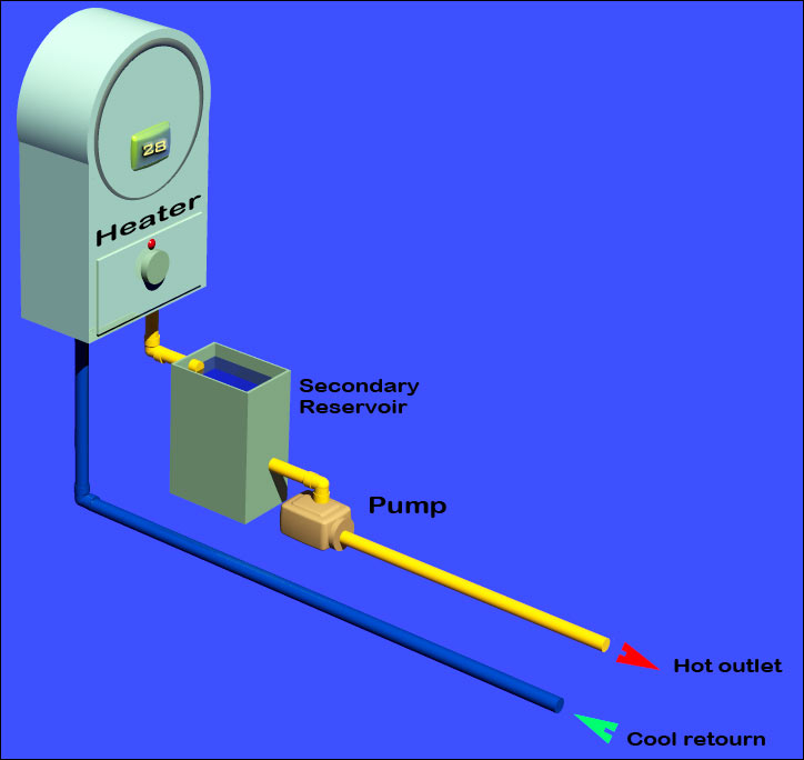 Obviously, the hot water outlet has to be connected to a hose and go into one or more reservoirs and return to the other connection (blue tube). As for the exposed part, a thick walled hose (plus insulation)- and for the part that goes into the reservoir, a rather thin walled hose is recommended. The water level at the secondary reservoir should be lower as shown (for illustration purposes only). To get the wanted temperature in the nutrient reservoir(s) simply turn the knob until it reaches the wanted temp in the nutrient reservoir. The electronics of the heater then automatically regulates the temp - as both (heater and nutrient reservoir) are different, yet relational. Last edited by Luches; 10-15-2009 at 07:43 AM.
|
|
#13
10-16-2009, 02:39 AM
|
|||
|
|||
|
I have never uses a tankless water heater but as I understand how they work, they only turn on when there is enough water flow. The water flows because of pressure, about 60-90 psi at our home. By simply drawing water from the secondary reservoir I don't see how that will create the water presser. I see the need for a primary reservoir, but even if the primary reservoir is significantly higher will that be enough pressure and or water flow to turn the unit on?
I can see having one reservoir higher than the heater with an overflow that runs through the heater and then into the secondary heater might work, if the heater turns on with water flow and presser is not required (I have no experience with tankless water heaters). If so, I would imagine that when the pump draws water from the secondary reservoir and fills the system it would run back into the primary reservoir. Then when the primary reservoir reaches the right height it will flow back through the heater from an overflow in that reservoir, then into the secondary reservoir again where it is pumped through the system again. It seems that there would be a need for 2 pumps to me. The primary tank that the hydroponic system overflows into needs to be lower than the system or it wont overflow. The heater needs to be below that one to allow gravity to feed it. Unless the pump is in the primary reservoir and runs the water through the heater into the secondary reservoir that would be positioned higher than the hydro system and a overflow in the secondary to feed the hydro system. Then the overflow in the system to drain back into the primary reservoir where it can be pumped back through the heater. I think I got it unless the heater requires presser to turn on, I am thinking an flood and drain type system also but don't really see a difference in that. Last edited by GpsFrontier; 10-16-2009 at 02:56 AM.
|
|
#14
10-16-2009, 03:40 AM
|
|||
|
|||
|
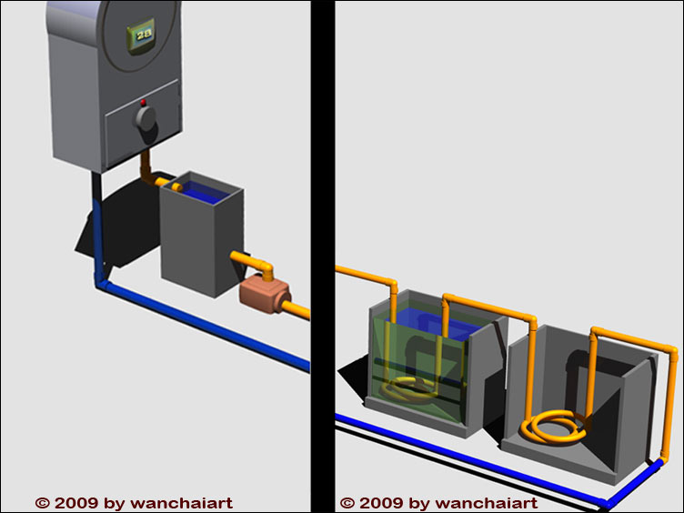
I guess I should have continued to draw the next part of the installation, as there is a huge misunderstanding of the actual concept and functioning.
Look, it is much simpler: 1. Firstly I was using (and still recommend) a 5L or 1-1/4 gallon reservoir as mentioned earlier - they are cheaper and use less power. But most importantly, they do not turn on by water pressure or flow, but in fact strictly thermostatically. 2. I called the secondary reservoir so because of it's relation to the 5L tank of the heater. 3. The circuit (actually not shown integrally) here is a separate and closed circuit, no nutrient actually flows through it, but tap water. The main hose only (connected to the heater's in- and outlet - as in yellow and blue) gets dropped (lays) inside one or several nutrient reservoirs and heats it indirectly. That is why I said that a thinner hose should be used inside the reservoir(s). In fact to better conduct and transmit the heat from the hose to the nutrient solution. 4. The "mechanics" of this concept are actually unbelievably simple and one tends to over-think it by anticipating possible errors. Just trust me, this system is thought trough very well and is working perfectly fine if understood and used in the right way. 5. One more hint, if the heater unit (secondary tank and pump also) are positioned at the same level (hight) of the outlet and inlet level (both are suposed to be at the same hight then) of the hose entering (and exiting) the the reservoir(s), it doens't need to be very powerfull. There are two options: running the pump by cycles or running it permanently. By cycle will save some energy and permanently will assure very stable temperatures of the nutrient solution.
|
|
#15
10-16-2009, 04:38 AM
|
|||
|
|||
|
by
Quote:
I am obviously not understanding the type of heater you are talking about. Quote:
Quote:
If it's a coil inside a nutrient solution I don't see a way to heat it without water flow through the coil and something controlling that water flow. I think I simply don't understand the type of heater you are using. Do you have a link to one?
|
|
#16
10-16-2009, 05:03 AM
|
|||
|
|||
|
Sorry,
I think I now understand. The secondary reservoirs position in the image was confusing as well as the lack of the other reservoirs, even though you had mentioned them. It looks as though in addition to the heater and the regular system pump it requires a pump that feeds the heater that would be on 24/7. There is water flow, to recirculate the water through the hose (coils) but the heater has no restrictions in regards to pressure. The main thing is that both the heater and the pump would need to be on 24/7 or at least all night and on a timer to turn them off when it becomes day.
|
|
#17
10-16-2009, 09:24 AM
|
|||
|
|||
|
I knew what I was talking about when I said that the design and the mechanics are unbelievably simple - I forgot to mention that it although has the potential to get a theoretical physicist in trouble
  Anyway I should have made the complete drawing in the first place. But it has been actually one more hour of work. But you should be less sceptic with me, I've build and have tested this design 25 years ago. No offense Dear, but you are anticipating too many if-then possibilities, which are 100% home made by your imagination. Nothing wrong though, with being sceptic and thus being able to anticipating mistakes and weak points in a design. Nothing wrong with anticipating - as long as one is right! Back to the design and the facts: Important: as we deal with a closed circuit, the pump sucks water out of the "secondary reservoir" (actually tank) and in the same time it pushes it through the circuit into the heater - and back in the secondary reservoir! Hence the secondary reservoir avoids build up of pressure (but allows a closed circuit) in the most simplest and effective way. The design works perfectly well with a heater that has a small tank, 5 Liter as I said. I am not sure if those are available IN US or AUS, - In Europe they're still popular an often in use. But I've found this from Australia, which actually is exactly the same: 5 Liter caravan heater I am quite sure that a normal tankless heater (the smallest available) will do the deal as well. Because this kind of heater has the same electronics, except that it is "flow triggered" as well. Btw: I've 3 Bathrooms and all have those kind of heaters installed. They are switched on permanently, but the so called grilon gets only triggered when: A. the water flows through and B. if heating of flowing water is required (thermostatically), - which is perfect for the purpose. PS: In action with my 1000 Liter reservoir, the 5 Liter Heater was switching on and off alternatively for a few minutes, to keep the 1000 Liter stable at 34.5°C. Consumption was acceptable too. Testing a tankless heater for the purpose shouldn't be rocket science. Just fix fittings to 2 PVC tubes, a pair of knees and fit a piece of hose to them, (putting a secondary tank in-between to avoid building up of pressure through expansion of hot water is strongly recommended) form some sort of coil with the hose and drop it in a bucket of cool water. Watch and learn... Last edited by Luches; 10-16-2009 at 09:53 AM. Reason: forgot the picture plus a few changes...
|
|
#18
10-16-2009, 06:11 PM
|
||||||
|
||||||
|
Quote:
Quote:
Quote:
Quote:
Quote:
Quote:
Thanks for your help!!!
|
 |
| Bookmarks |
|
|


 Linear Mode

